MR380E Didactic System of Domestic Energy Production Teaching Equipment Automatic Trainer
I. Product overview
1.1 Overview
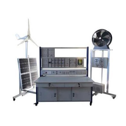
This training device system can simulate and demonstrate the process of wind power generation and solar power generation, so that students have a preliminary intuitive understanding of wind and solar hybrid power generation systems. The wind generator is driven by a blower, and the solar panel is driven by high-brightness LED lights. Through relevant experiments, cultivate students' corresponding knowledge and skills.
1.2 Features
(1) The training platform adopts the aluminum profile column frame structure, the measuring instrument and the training power supply are built-in and integrated, and the bottom is equipped with universal wheels. Each unit is flexible, easy to use, and not easy to damage. (2) The experimental circuits and devices are fully equipped and can be used in combination to complete the training content of various courses. (3) The training platform has a good safety protection system.
II. Performance parameters
(1) Wind power generation device: The fan unit adopts aluminum profile structure, the blower can be adjusted by 90 degrees in the horizontal direction, and the overall size is 1210*1210*2440mm (length, width and height) (2) Solar power generation device: all aluminum alloy structure, the angle of the photovoltaic panel can be adjusted, the simulated light source can be adjusted at 120 degrees in the vertical direction, and the overall size is 1500*1500*2750mm (length, width and height) (3) Training platform size: aluminum profile frame structure, aluminum alloy hanging box unit form, with universal wheels at the bottom, dimensions 1610mm×800mm×1700mm (length, width, height) (4) The parameters of a single solar panel are as follows: Rated peak power: 30W Short circuit current: 1.9A Maximum current: 1.71A Maximum voltage: 17.6V Short circuit current: 1.87A Open circuit voltage: 21.6V (5) Fan parameters: Fan type: horizontal axis facing direction Speed: 1310 RPM Motor power: 0.7KW Voltage: 220V/50Hz Air volume: 10600m³/h (6) Technical parameters of battery: Voltage: 12V Capacity: 40Ah Battery loss: 10V±1V Executive standard: GB/T 9535 Relative humidity: 35~85%RH (no condensation) (7) Working environment: Temperature -10~+40℃Temperature≤80℃ Ambient air: no corrosive, combustible gas, no large amount of conductive dust (8) Power supply: Power consumption: ≤5000W, Power supply: AC120±5%, Power supply: single-phase three-wire AC120±5%, 50HZ Working method: continuous (9) Total weight: 200Kg
III. System introduction
3.1introduction
This system is divided into four parts: wind power generation system, photovoltaic power generation system, control system and inverter system. The wind power generation system is composed of blower, generator, and battery pack. The photovoltaic power generation system consists of a simulated light source device, photovoltaic panels and battery packs. The control system is composed of wind and solar hybrid controllers. The inverter system consists of a power frequency inverter, a rectifier filter unit, a DC-DC conversion module and a load unit. 1. Simulate wind power generation equipment; this system uses horizontal axis permanent magnet synchronous generators, uses a blower to simulate natural wind, and adjusts the position of the blower to simulate changes in wind direction and wind changes to detect the power generation effect under corresponding conditions. 2. Simulated photovoltaic power generation system: This system uses 4 30W monocrystalline silicon solar panels, which can be connected in series and parallel according to different system voltages. The simulated solar device consists of 4 halogen lamps with adjustable brightness, which can be adjusted with photovoltaic panels. To simulate the position of sunlight, it is convenient to simulate the demonstration of various sunshine conditions. 3. Battery pack: It is composed of 4 12V/40AH maintenance-free sealed batteries, which can be used in 12V200AH system in parallel, or used in 24V/100AH system in series, which can deepen the understanding of battery series and parallel applications. 4. Controller hanging box: This hanging box uses an industrial charging controller, including an interface for data collection through a PC, which can control the power generated by the wind turbine and photovoltaic panels to charge the battery. The LCD panel can be viewed System operating parameters and user parameters can be set by themselves, with perfect overcharge and overcurrent protection functions. 5. Inverter hanging box: 24V voltage intelligent identification industrial frequency inverter, output voltage AC110V, continuous power 600W, peak power 1000W. The conversion efficiency is greater than 90%, and the low-voltage automatic alarm. 6. Instrument hanging box; real-time display of power generation voltage, power generation current, charging voltage, charging current, inverter voltage, and inverter current. 7. Terminal load hanging box: including resistance, inductance and capacitance loads, different types of load tests are carried out on the 110V alternating current converted by the inverter. 8. Rectifier filter hanging box: use power diodes to form a bridge rectifier circuit to convert alternating current into direct current, and include inductance and capacitance for filtering. 9. DC-DC conversion module: can convert 5-30V voltage into 0.5-30V voltage.
3.2 Training table
The training table is supported by aluminum profile columns, and the bottom universal wheels are braked, which can be moved and positioned flexibly. The desktop adopts a 25mm-thick high-density substrate, and the surface is treated with high temperature and high pressure fireproof board veneer. It is equipped with 2 three-section guide rail drawers and 2 sliding door bottom cabinets. The structure is firm and beautiful.
3.3 Power control screen configuration
(1) Voltmeter and ammeter do measurement display and output indication. (2) Equipped with power indicator light and safety power output terminal. (3) Built-in AC power supply with short circuit protection function.
3.4 Supporting device
(1) 1 controller hanging box
Instructions: 1. Operation instructions ①Key function description 0K enter the next menu or confirm parameter settings “ ”Reduce the value when switching between the same level menus or setting parameters (long press for more than two seconds to quickly change the value) “ ”Increase the value when switching between the same level menus or setting parameters (long press for more than two seconds to quickly change the value) “Esc”Return to the previous menu or exit the command 2. Modify parameter operation instructions The user can manually set the parameters shaded in gray in the above figure according to the system configuration ②Parameter setting steps Press the OK button to enter the parameter setting, the highest digit of the set parameter value flashes Decrease or increase the flashing digits through the and keys The numbers are modified sequentially from left to right. After modifying a digit, press OK to skip to the next digit. When the last digit is modified, press OK to save, and press ESC to exit the modification. ③Parameter browsing 1.: BAT Normal **V **A **W
BAT- battery terminal information
The upper right has the following display: Low-Low battery Normal-The battery is normal Full—The battery is full **V-Battery voltage **I-Battery charging current **W-Battery charging power 2. Solar:NIGHT **V**A**W
Solar:Photovoltaic Information The upper right has the following display DAY-During the day (the photovoltaic voltage is higher than the light control point voltage Lon), this display has a 1 minute delay. After the controller is turned on, the default is DAY, analyze the current environment, and automatically display after 1 minute
NIGHT-At night (the photovoltaic voltage is lower than the light control point voltage Loff), this display has a 1 minute delay. **V—Photovoltaic charging voltage **I—Photovoltaiccharging current **W—Photovoltaic charging power
3. Wind: MS-OFF **V**A**W wind:Fan information No display in the upper right corner under normal working conditions. If MS-OFF is displayed in the upper right corner, it means that the fan charging switch is off (that is, the "M-SW" in the fan information is in the "OFF" state) **V—Fan input voltage **A—Fan input current **W—Fan input power
4. Output: Mode2 **V**A**W Output:Load output information The upper right corner shows the output mode, Model means that the load output is now mode 1, and so on **V—Load output voltage **A—Load output current **W—Load output power 5. In Power: **W In-Power Total input power
6. Total Energy **kWh Total Energy-Total power generation This value is a cumulative value, if you need to clear it, please set "Ener" in 3.4, Note: If cleared, the total power generation and load output power will be cleared at the same time.
7.Output Energy **kWh Output Energy—Load output power This value is a cumulative value, if you need to clear it, please set "Ener" in 3.4, Note: If cleared, the total power generation and load output power will be cleared at the same time.
8. Temperature: NORMALT:**C Temperature- Temperature information NORMAL:Power device temperature is normal HIGH:High temperature of power device OTP:Power device over temperature protection ERROR:Temperature detection failure T:**C **Celsius 9. Device Address Address:1 Device Address—MODBUS The device address under the standard protocol (the device address can be set in 3.4)
State: Normal
C:**** L:**** State Controller charge and discharge status Normal: The battery is normal
HVol: The battery is normal C:**** Countdown to controller charging back to normal L:*** Countdown to normal load discharge
Errors: (0/0)
No Errors. Errors:error code 0/0—Total number of faults For example: 2/4 means there are 4 faults in total, and the second line is displaying the second of these 4 faults. Press the OK key to enter the state of browsing the fault codes. You can browse all the fault codes currently appearing through the left and right keys. When No Errors is displayed on the second line, press the OK key to enter the system information interface. NO BATTERY—The battery is not detected or the battery voltage is too low SHORT LOAD—Load short circuit or excessive load current SOLAR OVER V—Photovoltaic voltage is too high LOAD OVER V—The load voltage is too high TEMP ERROR—Temperature sensor error EEPROM ERROR—Data memory error NO Errors—No error (2) 1 inverter hanging box (Note: The input voltage is not allowed to exceed DC 24V)
(3) 4 instrument hanging boxes
(4) 3 load hanging boxes
(5) 1 rectifier filter hanging box
DC-DC conversion hanging box
(6) 40 4mm safety electrical cable
IV. Can complete the training content
(1) Battery characteristic experiment: 1) Electrical parameter measurement 2) Series and parallel connection of batteries (2) Charge controller experiment: 1) Reverse connection protection experiment 2) Overcharge protection experiment of the controller to the battery 3) Overdischarge protection experiment of the controller to the battery 4) Anti-reverse charging experiment (3) Simulation of wind power generation system experiment (4) Wind energy charging control experiment (5) Measurement experiment of power generation (6) Test experiment of open circuit voltage of photovoltaic panels (7) Short-circuit current test experiment of photovoltaic panels (8) Photovoltaic panel power measurement experiment (9) The maximum power measurement experiment of photovoltaic panels under different illumination (10) Photovoltaic panel output characteristic experiment (11) Photovoltaic battery panel charging control principle experiment (12) Anti-reverse charge experiment of photovoltaic panels (13) Series and parallel experiments of photovoltaic panels (14) Basic principle experiment of inverter (15) Simple inverter output waveform test experiment (16) Series and parallel experiments of photovoltaic panels (17) Basic principle experiment of inverter (18) Simple inverter output waveform test experiment (19) Experiment of AC load driven by inverter power supply (20) Wind and solar hybrid power generation experiment