MR022R Conditioning of room air Educational Equipment Vocational Training Equipment Refrigeration Trainer Equipment
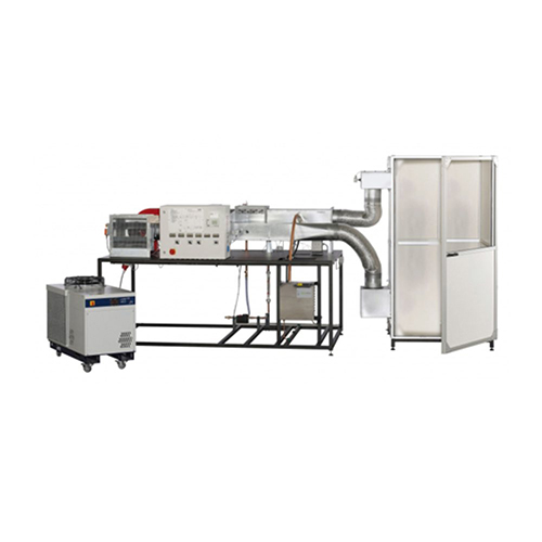
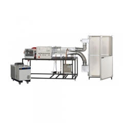
Air conditioning system consisting of industrial components including direct evaporator and vapour humidifier Features - air conditioning system with steam humidifier - wide experimental program for conditioning of room air - representation of the thermodynamic principles in the log p-h and h-x diagram - dynamic recording of the refrigerant mass flow rate Learning objectives/experiments - air conditioning of room air -- setup of an air conditioning system: main components and their function -- variables in air conditioning
-- measure temperature and air humidity -- effect of the air flow -- changes of state in the h-x diagram
 - setup of a refrigeration system: main components and their function - measurements in the refrigeration circuit -- cyclic process in the log p-h diagram -- determine heating and cooling capacities
Specification - effect of typical air conditioning system components on the conditioning of room air - air conditioning system with open air duct, air cooler, steam humidifier, fan, air preheaters and reheaters - all components can be switched on and off individually - determination of the volumetric air flow rate by differential pressure measurement using an inclined tube manometer - combined sensors for the air humidity and temperature before and after each stage - sensor for the pressure and temperature of the refrigerant - refrigerant mass flow rate precisely calculated via software - oftware for data acquisition via USB under Windows 8.1, 10 - refrigerant: R513A, GWP: 631
NAVAL CONDITIONING UNIT
- setup of a refrigeration system: main components and their function - measurements in the refrigeration circuit -- cyclic process in the log p-h diagram -- determine heating and cooling capacities
Specification - effect of typical air conditioning system components on the conditioning of room air - air conditioning system with open air duct, air cooler, steam humidifier, fan, air preheaters and reheaters - all components can be switched on and off individually - determination of the volumetric air flow rate by differential pressure measurement using an inclined tube manometer - combined sensors for the air humidity and temperature before and after each stage - sensor for the pressure and temperature of the refrigerant - refrigerant mass flow rate precisely calculated via software - oftware for data acquisition via USB under Windows 8.1, 10 - refrigerant: R513A, GWP: 631
NAVAL CONDITIONING UNIT
The unit has been designed for the study and practice of air conditioning units
of the air, using a refrigeration and dehumidification circuit applied to a
air duct.
The device can be used in accordance with the processes of:
• ventilation
• cooling down
• drying
The complete instrumentation allows the measurement and calculation of all
unit operating parameters, such as:
• power absorbed by the post-heating and by the fan

• thermo-hygrometric characteristics of the air at each point of the duct
conditioning
• characteristics of the refrigerant fluid (ecological type) of temperature e
pressure in every point of the refrigeration circuit
• refrigerator performance
In addition, it is possible to study air conditioning in different operating conditions,
by varying the air flow in the air conditioning duct and the average flow rate of
evaporator refrigeration.

Predisposition for interfacing with a computer
The plant is built already prepared for the installation of a series of
transmitters (see optional) that send to the "Acquisition Module e
Data Recording "(optional CE35g) the values of the operating parameters
of the plant; these values are then processed by a computer, which can
be quoted on request, to view the results through tables and graphs
of Guided Experiences.
It is explicitly noted that only one "Acquisition and Registration Form
Data "can be used to interface all systems to a computer
computerizable of a laboratory. In addition, a
data processing software, useful for processing and representation
graphics of some Guided Experiences.
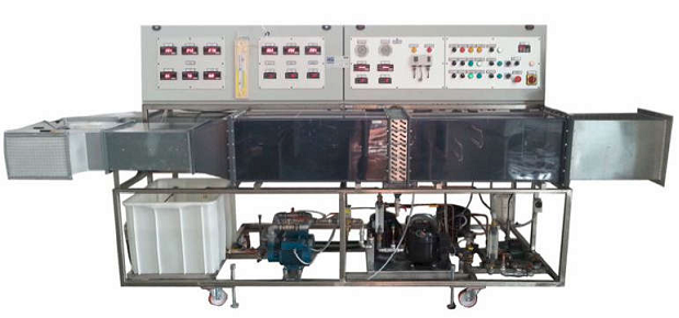
 DESCRIPTION
Air conditioning duct
It includes a large duct (500 x 220 mm) for
best represent the real units and is divided into several sections of
air conditioning, which are placed in sequence in the duct itself.
These sections are as follows:
• filter section: easy to remove, with acrylic support, completely
washable or cleanable by blowing air
• cooling section (summer conditioning), made up of copper coils
and aluminum fins. The inlet temperature of the chilled water can
vary between 6-8 ° C, while the output one can vary between 9-12 ° C
• a differential pressure gauge for measuring the air flow in the duct
aspiration

• a centrifugal fan with always variable speed with 0-700 m³ / h
• post-heating section made up of adjustable electric resistances
• calibration damper for varying the air flow
A series of probing thermometers and hygrometers allow users the
change in the thermo-hygrometric state of the air in the various sections of the duct.
The cooling and drying sections are equipped with a small tank
for the collection of condensate or excess water that is conveyed
through a drain for the drain.

Refrigeration circuit
To create the cooling air of a compression refrigeration circuit
It is used:
• a refrigeration compressor: 0.5 kW 33 cm³ 2.2 kW
• a non-return valve
• a sea water / refrigeration liquid condenser
• an expansion valve
• a valve for regulating the refrigerant fluid to the evaporator, in order to
adjust the cooling intensity
• a coolant / fresh water evaporator
• refrigerant fluid: R134a
A pressure switch stops the compressor motor when the pressure exceeds
set points.
The refrigerant circuit is equipped with the necessary instrumentation to determine the
refrigeration cycle.

Instrumentation
The standard equipment included in the system is as follows:
Air treatment duct
• no. 4 thermometers for measuring the air temperature (inlet and
exit from each treatment section)
• no. 4 hygrometers for measuring relative humidity (input and output from each
treatment section)
• a differential pressure gauge for measuring the air flow
• measurement of the electrical absorption of the post-heating resistances
Refrigeration circuit
• no. 4 thermometers for measuring the evolution temperature
refrigerant in the refrigeration cycle
• no. 2 pressure gauges for measuring the freon pressure in the circuit
refrigeration
• special seats for measuring the inlet water temperature
evaporator and condenser outlet
• no. 2 flow meters to measure the water flow rate in the evaporator e
capacitor
Refrigeration panel unit
• pressure switches for the refrigeration unit
• safety pressure switch for refrigeration units
• anti-freeze safety thermostat for evaporator water
• no. 2 thermostats to control the exchange water temperature of the
Conditioner
Air conditioner electrical panel
• switch
• analog indicator for displaying the current absorbed by the post-heating
• digital indicators of temperature and humidity of the air conditioning
• switch for fan speed
• switch for starting the compressor
• switch for post-heating air adjustment
Pumps
Two pumps (one in work and one in stand-by conditions) for sea water:
centrifugal type, 3-phase electric motor
Two pumps (one in work and one in stand-by conditions) for fresh water
(chilled water): centrifugal type, 3-phase electric motor
Metallic structure
The unit is mounted on a steel support frame, including wheels
swiveling to facilitate movement and positioning.
Transmitters and Management Software
A series of transmitters send to the "Acquisition and Registration Form
Data the following values:
• evolving air flow in the treatment duct
• air temperature entering the treatment
• humidity in the air entering the treatment
• pre-humidification section air temperature
• pre-humidification section air humidity
• air temperature leaving the treatment
• humidity in the air leaving the treatment
• current absorbed by the fan and by the post-heating coil
The management software, stored on a CDROM, includes programs for
computer (run type) developed in LabVIEW environments. Allows the
control, monitoring, acquisition and processing of incoming measures
from the plant. The video (not supplied with this option) shows a picture
synoptic that reproduces the main components of the system with indication
measurements in real time.
The most significant parameters relating to the operation of the system are
displayed on tables and graphs.
The LabVIEW system is developed in a Windows environment.
The software also allows the simulation of faults: a screen appears in
which is made a list of possible failures on the system through which the
By clicking on a type of fault, the teacher can analyze the
consequences that the same has created for the plant.
The acquired measurements are in fact automatically modified according to the
type of fault introduced.
Data Acquisition and Registration Module
Automatic data acquisition and recording system used to convert i
signals coming from electronic transmitters placed on a signal system
digital processed by a Personal Computer.
The system is capable of acquiring 8 analog signals with 4 input ranges
programmable, data transfer takes place at high speed via cable
USB.
The acquirer is supplied with software that, loaded on the computer, allows
real-time video recording of the trend over time of the variables
acquired; the recordings made can then be printed or stored.
The recorder function is very flexible, allowing you to vary:
· The number of recorded quantities
· The time scale
Units of measurement (engineering or percentages)
The duration of the registration
· The sampling frequency
The system consists of a table container, dimensions 280x200x150 (h)
[mm], with:
· On the front: the identification plate
· On the back: the “AMP” connector for input of the analog signals, and the
USB (female) output connector. The system is supplied complete with cables
analog signals from the field and the USB cable for the
computer connection.
Inside are:
Main technical features:
Absorbed power 9 [W]
· Computer powered via the USB cable
· working conditions
- temperature -40 ÷ 70 [° C]
- humidity 10 ÷ 90% (non condensing)
Didactic support
Two Technical Manuals, included in the supply, developed as follows:
• Equipment Description
• Installation, use and maintenance
• Guided experiments
In addition, a disk in possession of a
data processing software; this software is a package developed by US
in Excel, then in Windows, which collects the data entered
by students by hand (or acquired in automatic mode through optional), them
processes and displays them in graphic form.
Requested services
Electrical: standard: 400 Vac ± 10% 3 phases, 50 Hz, 1.2 kVA with earth connection
according to CEI standards.