MR-HM 150.12 Vertical Flow From A Tank Measurement educational equipment teaching didactic equipment fluid mechanics lab equipment Description
• determination of the diameter and velocity of the outlet jet
• study of openings with different inlet and outlet contours
• determining the contraction coefficient
Pressure losses in the flow from tanks are essentially the result of two processes: the jet deflection upon entry into the opening and the wall friction in the opening. As a result of the pressure losses the real discharge is smaller than the theoretical flow rate.
MR-HM 150.12 determines these losses at different flow rates. Different diameters as well as inlet and outlet contours of the openings can be studied. Additionally, the contraction coefficient can be determined as a characteristic for different contours.
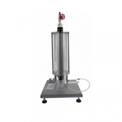
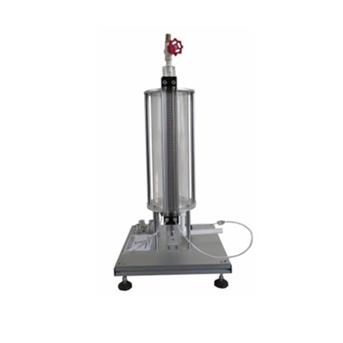
The experimental unit includes a transparent tank, a measuring device as well as a Pitot tube and twin tube manometers. An interchangeable insert is installed in the tank’s water outlet to facilitate the investigation of various openings. Five inserts with different diameters, inlet contours and outlet contours are provided along with the unit. The issued water jet is measured using a measuring device. A Pitot tube detects the total pressure of the flow. The pressure difference (read on the manometer) is used to determine the velocity.
The tank is fitted with an adjustable overflow and a measuring point for static pressure. In this way, the level can be precisely adjusted and read on the manometer. The experimental unit is positioned easily and securely on the work surface of the MR-HM 150 base module.
The water is supplied and the flow rate measured by MR-HM 150. Alternatively, the experimental unit can be operated by the laboratory supply.
Learning objectives/experiments
• study of the outlet jet (diameter, velocity)
• determination of pressure losses and contraction coefficient for different outlet contours
• determination of flow rate at different discharge heads
Specification
[1] study of pressure losses in vertical flows from tanks
[2] determining the contraction coefficient for different contours and diameters
[3] tank with adjustable overflow
[4] 5 interchangeable inserts with different contours
[5] measuring device for determining the jet diameter
[6] Pitot tube for determining the total pressure
[7] pressure display on twin tube manometers
[8] flow rate determined by MR-HM 150 base module
[9] water supply using MR-HM 150 base module or via laboratory supply Technical data
Tank
• capacity: approx. 13L
• overflow height: max. 400mm
• max. flow rate: 14L/min
Inserts
Inside diameters: d1=inlet, d2=outlet
• 1x cylindrical hole, d=12mm
• 1x outlet from the insert: cone d1=24mm, d2=12mm
• 1x inlet to the insert: orifice plate d1=24mm, d2=12mm
• 1x inlet to the insert: cone d1=30mm, d2=12mm
• 1x inlet to the insert: rounded, d=12mm
Measuring ranges
• pressure: 500mmWS
• jet radius: 0…10mm
LxWxH: 400x400x830mm
Weight: approx. 18kg
Required for operation
MR-HM 150 (closed water circuit) or water connection,
drain
Scope of delivery
1 experimental unit
5 inserts
1 set of hoses
1 set of instructional material