MR-HM 150.07 Bernoulli's principle educational equipment vocational training equipment fluid mechanics lab equipment
1. Equipment introduction
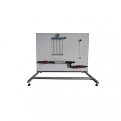
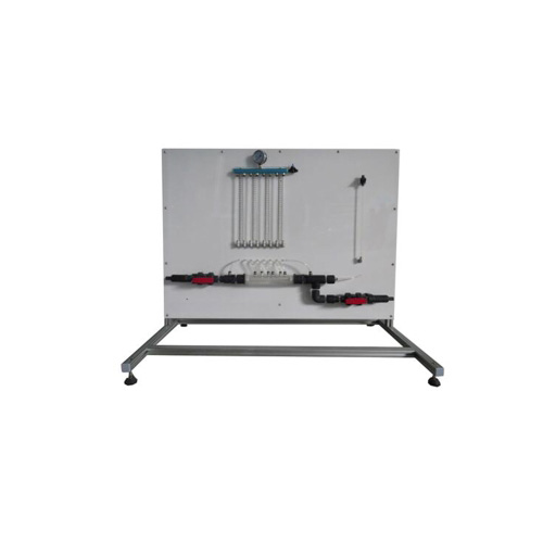
MR-HM 150.07 is an experimental device used to explore Bernoulli's law. The measuring object is a venturi tube with 6 pressure measuring points. These 6 static pressures are displayed on one panel through 6 water pressure gauges. The total pressure can also be measured by an axially movable probe at various locations throughout the venturi and indicated on a second water pressure gauge. The probe is sealed by a compression rubber ring to ensure no leakage during measurement.
Water can be supplied by the Fluid Dynamics Basic Module or obtained directly from the laboratory's main water supply. Is capable of constructing a closed water circulation system.
2. Technical data
Water manometer 6 times: 300 mm water column
Total pressure pipe manometer 1 times: 530 mm water column
Venturi flow meter nominal diameter: 28.4 mm
Minimum diameter: 14mm
Overall dimensions (length x width x height): 1100 x 640 x 900mm
Weight: 40kg
3.Components
No Name No Name
1 Assembly board 6 Measuring point
2 Single water pressure gauge 7 Compression rubber ring
3 drain pipe 8 Hose connection, water supply port
4 outlet float valve 9 Water inlet ball valve
5 Venturi tube with 6 measuring points 10 Six-link water pressure gauge
4. Experiment list
Experiment 1 Proof of Bernoulli’s Law
Experiment 2 Pressure measurement of venturi tube
Experiment 3 Determination of flow rate factor K