MR-HM380 Cavitation in Pumps didactic equipment vocational education training equipment fluid mechanics lab equipment Description
• visualisation of cavitation effects in a transparent pump
• continuously adjustable pump speed
• closed water circuit
One of the most common causes of cavitation effects are fast moving objects in the water, such as the impellers of a centrifugal pump. If cavitation occurs on the impeller, the high mechanical stress sometimes results in separation or deformation of particles from the surface. In addition to the impeller geometry, intake pressure and temperature are also relevant for the occurrence of cavitation.
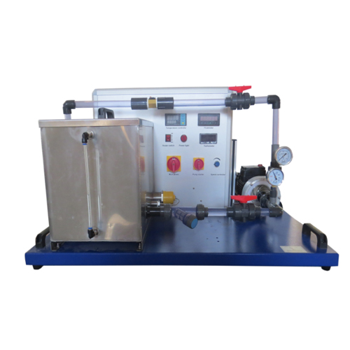
The MR-HM 380 unit can be used to demonstrate cavitation effects on impellers of centrifugal pumps. Pump
housing and the pipe at the inlet side of the pump are made of transparent plastic in order to visualise the cavitation processes. It is possible to capture excellent images of the vapour bubbles by taking photographs with short exposure times (flash).
In order to influence the flow velocity at the impeller blades, the speed can be changed within a wide range via a frequency converter. Valves at the inlet and outlet of the pump enable the flow rate and pressures to be adjusted accordingly.
Pressures on the inlet and outlet side are displayed on two manometers. Also displayed are the water temperature in the tank, flow rate and pump speed. The water temperature can be controlled and the tank is fitted with a heater. The water is cooled via the water supply. Learning objectives/experiments
• formation of cavitation
• observation of cavitation effect
• how speed, inlet pressure, flow rate and temperature affect cavitation
Specification
[1] visualisation of cavitation in centrifugal pumps
[2] transparent pump housing and pipe at the inlet side
[3] open impeller to observe the blades during operation
[4] continuously adjustable pump speed via frequency converter
[5] temperature control via heater and external cooling via water supply
[6] flow measurement using rotameter
[7] display of the pressures at inlet and outlet side of the pump via manometers
[8] digital display of speed, water temperature in the return and flow rate
[9] closed water circuit with tank and temperature display
Technical data
Centrifugal pump with drive motor
• power consumption: 0,37kW
• speed: 500…3300min-1
• max. flow rate: 70L/min
• max. head: 13m
Tank: 20L
Measuring ranges • pressure (inlet): -1…0bar
• pressure (outlet): 0…1,5bar
• temperature: 0…100°C
• flow rate: 10…140L/min
230V, 50Hz, 1 phase
LxWxH: 1000x630x590mm
Weight: approx. 65kg
Required for operation
water connection: approx. 100L/h
drain
Scope of delivery
1 experimental unit
1 set of hoses
1 set of instructional material