MR-HM 150.29 Energy losses in piping elements didactic equipment educational equipment teaching fluid mechanics laboratory equipment Description
• pressure losses in various pipe fittings and in the ball valve
• precise pressure measurement via annular chambers
• visualisation of differential pressures on manometer panel
When water flows through a pipe system, the flow resistances causes pressure losses to occur at pipe fittings and valves and fittings.
The HM 150.29 unit can be used to investigate and visualise the pressure
losses in pipe elements. The experimental unit can be used to assess how different pipe geometries affect the flow.
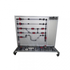
The HM 150.29 experimental unit comprises a pipe section containing several pipe elements with different flow resistances, as well as a contraction and enlargement piece. There is also a ball valve integrated in the pipe. There are pressure measuring points with annular chambers upstream and downstream of the pipe elements, which ensure accurate pressure measurement.
The pressure measuring points can be connected in pairs to a 6 tube manometers in order to determine the pressure loss of a pipe element. The experimental unit is positioned easily and securely on the work surface of the HM 150 base module. The water is supplied and the flow rate measured by HM 150. Alternatively, the experimental unit can be operated by the laboratory supply.
Learning objectives/experiments
• investigate pressure losses at segment bend and bends
• investigate pressure loss at contraction and enlargement
• pressure loss at a ball valve and determination of a simple valve characteristic
Specification
[1] investigation of the pressure loss in flow through pipe fittings and in the ball valve
[2] sudden contraction and sudden enlargement, pipe bend, segment bend, pipe angle and ball valve as
measurement objects
[3] annular chambers allow precise measurement of pressure
[4] 6 tube manometers for displaying the pressures
[5] Bourdon tube pressure gauge for pressure measurement
[6] flow rate determined by base module HM 150
[7] water supply via HM 150 or via laboratory supply Technical data
Pipe, PVC
• inner diameter: 17mm
Pipe elements, PVC
Inner diameter: d
• sudden contraction: from d=17 to d=9,2mm
• sudden enlargement: from d=9,2 to d=17mm
• segment bend: d=17mm, 90°
• pipe angle: d=17mm, 90°
• narrow pipe bend: d=17mm, r=40mm, 90°
• wide pipe bend: d=17mm, r=100mm, 90°
Measuring ranges
• pressure:
· 1x 0…1,6bar
· 6x 0…0,03bar
LxWxH: 840x675x930mm
Weight: approx. 28kg
Required for operation
HM 150 (closed water circuit) or water connection,drain
Scope of delivery
1 experimental unit
1 set of hoses
1 set of instructional material