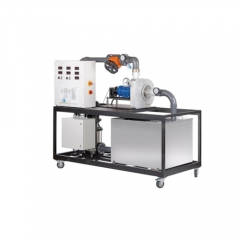
MR-HM 430C Francis turbine trainer vocational training equipment educational equipment teaching fluid mechanics lab equipment Description
• characteristics of a powerful Francis turbine
• optimal view of the operating area of the turbine
• adjustable guide vanes for setting the output The Francis turbine belongs to the reaction turbines which convert pressure energy of the working medium into kinetic energy in the guide vanes and in the rotor. Francis turbines are used for medium heads. The turbine power is controlled by adjusting the guide vanes. In practice, Francis turbines are used in run-of-river power plants and in pumped storage plants. SR-HM430C enables examinations of the function and operating behaviour of a Francis turbine. The dimensions of the trainer guarantee realistic measured values. The closed water circuit consists of a tank with optional cooling, a centrifugal pump and a flow control valve for adjusting the inlet pressure. The transparent
operating area of the turbine enables an optimal view of water flow, rotor and guide vanes during operation. By adjusting the guide vanes the angle of attack, the cross-section and thus the output of the turbine are changed. An asynchronous machine is used as a generator for loading the turbine. A pump with variable speed via frequency converter provides for an energy efficient operation.
The speed of the turbine is recorded by means of an inductive, non-contact position sensor at the generator shaft. The generator is equipped with a pendulum bearing and with a force sensor to determine the torque. The pressures at the inlet and outlet of the turbine, the temperature and the flow rate are recorded by sensors. The measured values are displayed digitally and can be processed further on a PC. The output data of the examined turbine are determined and can be represented by characteristic curves. Learning objectives/experiments
• investigation of the conversion of hydraulic into mechanical energy
• determination of the mechanical power and hydraulic power of the turbine
• determination of efficiency
• recording of characteristic curves
• investigation of the influence of the guide vane position
• velocity triangles
Specification
[1] investigation of a Francis turbine
[2] closed water circuit with pump, motor, flow control valve and tank with optional cooling
[3] pump with variable speed via frequency converter
[4] adjustment of flow rate via flow control valve
[5] loading the turbine by use of the asynchronous machine as generator
[6] rotor and guide vanes of the turbine completely visible
[7] adjustable guide vanes for setting different angles of attack
[8] non-contact speed measurement at the generator haft and force sensor for measuring the driving torque
[9] digital display for temperature, flow rate and ressures (additional manometer within scope of supply), speed, torque and electrical power of generator
SR-HM170 Open wind Tunnel
Description
A wind tunnel is the classic experiment system for aerodynamic flow experiments. The model being studied remains at rest while the flow medium is set in motion, and thus the desired flow around the model is generated.
SR-HM170 is an “Eiffel” type open wind tunnel used to demonstrate and measure the aerodynamic properties of various models. For this purpose, air is drawn in from the environment and accelerated. The air flows around a model, such as an aerofoil, in a measuring section. The air is then decelerated in a diffuser and pumped back into the open by a fan. The carefully designed nozzle contour and a flow straightener ensure a uniform velocity distribution with little turbulence in the closed measuring section. The flow cross-section of the measuring section is square. The built-in axial fan with outlet guide vane system and a variable-speed drive is characterised by an energy-efficient operation at high efficiency. Air velocities of up to 28m/s can be reached in this open wind tunnel. The trainer is equipped with an electronic two-component force sensor. Lift and drag are detected and displayed digitally. The air velocity in the measuring section is displayed on the inclined tube manometer. The tube manometers HM 170.50 or the electronic pressure measurement HM 170.55 are recommended for measuring the pressure distribution on bodies.
By using the system for data acquisition HM 170.60, the measured values for velocity, forces, moment, displacement/angle, and differential pressure can be transferred to a PC where they can be analysed with the software. Our price didn’t contain PC.
Extensive accessories allow a variety of experiments, for example lift measurements, pressure distributions, boundary layer analysis or visualisation of streamlines.
Technical details
Specification
experiments from the field of aerodynamics and fluid mechanics with an “Eiffel” type wind tunnel
wide range of accessories available
transparent, closed measuring section
inlet contour, nozzle and diffuser made of GRP
variable-speed fan motor for energy-efficient operation
flow straightener reduces turbulence
inclined tube manometer for displaying the air velocity
electronic two-component force sensor for measuring the drag and lift forces
digital display of drag and lift on the measuring amplifier
angle display on a scale
optional: display of measured values for velocity, forces, moment, displacement/angle, and differential pressure using system for data acquisition HM 170.60
Technical data
Measuring section
flow cross-section WxH: 292x292mm
length: 420mm
wind velocity: 3,1…28m/s
Axial fan
power consumption: 2,2kW