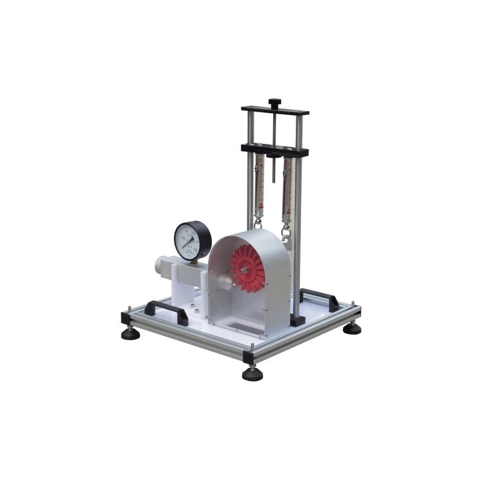
MR-HM 150.19 Operating principle of a Pelton turbine laboratory equipment educational equipment teaching fluid mechanics lab equipment Description • model of an impulse turbine • transparent operating area • adjustable nozzle cross-section • loading by band brake Water turbines are turbomachines utilising water power. The Pelton turbine is a type of impulse turbine; such turbines convert the pressure energy of water into kinetic energy entirely in the distributor. During the conversion, the water jet is accelerated in a nozzle and directed onto the blades of the Pelton wheel tangentially. The water jet is redirected by approximately 180° in the blades. The impulse of the water jet is transmitted to the Pelton wheel. MR-HM 150.19 is a model of a Pelton turbine demonstrating the function of an impulse turbine. The experimental unit consists of the Pelton wheel, a needle nozzle used as distributor, a band brake for loading the turbine and a housing with a transparent front panel. The transparent cover enables to observe the water flow, the Pelton wheel and the nozzle during operation. The nozzle cross-section and thus the flow rate are modified by adjusting the nozzle needle. The turbine torque is determined by force measurement on a band brake and is read on spring balances. For measuring the rotational speed, a noncontact speed sensor, e.g. MR-HM 082, is required. A manometer shows the water pressure at the turbine inlet. The experimental unit is positioned easily and securely on the work surface of the MR-HM 150 base module. The water is supplied and the flow rate measured by MR-HM 150. Alternatively, the experimental unit can be operated by the laboratory supply. Learning objectives/experiments • design and function of a Pelton turbine • determination of torque, power and efficiency • graphical representation of characteristic curves for torque, power and efficiency Specification [1] function of a Pelton turbine [2] transparent front panel for observing the operating area [3] loading the turbine by use of the band brake [4] adjustable nozzle needle for setting different nozzle cross-sections [5] marking on brake drum for non-contact speed measurement [6] instruments: spring balances for determining the torque, manometer shows pressure at turbine inlet [7] flow rate determination by base module MR-HM 150 [8] water supply using base module MR-HM 150 or via laboratory supply Technical data Pelton turbine • output: 5W at 500min-1, approx. 30L/min, H=2m • Pelton wheel · 14 blades · blade width: 33,5mm · external Ø: 132mm Needle nozzle • jet diameter: 10mm Measuring ranges • force: 2x 0…10N • pressure: 0…1bar LxWxH: 400x400x620mm Weight: approx. 15kg Required for operation MR-HM 150 (closed water circuit) or water connection,drain Scope of delivery 1 experimental unit 1 set of instructional material