3GHz RF Educational Training System
I.Overview
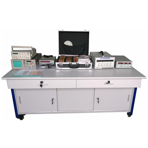
RF teaching practice system mainly for the colleges and universities to communication engineering, electronic engineering, microwave electronic circuit, microwave technology, and other professional experiment teaching and curriculum design, graduation design, students' secondary development and design. RF teaching practice system during the RF signal generation and transformation, mixing, filtering, amplification, emission, transmission, reception, demodulation process, so that students can learn more about 1 GHz frequency within RF system of basic structure, working principle, simulation analysis, testing instrument and measuring skill knowledge, mastery of time domain and frequency domain, the transmission line, wave propagation and antenna, RF module and radio frequency communication and other basic concepts, and learn to use important RF test instrument.
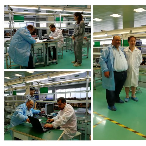
RF teaching practice system adopts the modular structure design, flexible connection mode for training of experimental training provides a very convenient, flexible assembly, satisfied the various institutions of the experimental teaching requirements, and more exercise the student's beginning ability, thinking ability and innovation ability, in addition, the system module circuit all adopt the microstrip circuit design, can be clearly observed all microstrip circuit structure; Transparent organic glass plate application, make each module legerity, beautiful, and can be integrated in an instrument box, easy to carry and transportation.
RF teaching practice system include the following parts: camera, TV modulator, mixer, RFamplifier, VCO, phase lock loop, antenna, intermediate frequency amplifier, image demodulator, display, 10 dB directional coupling can form a video image transmission system. Image signal after amplitude modulation (am) and the frequency conversion, the antenna launch out, the image signal by receiving after demodulation can let a person intuitive, real-time see clear image. All, video system in a complete set of system plays a very important role. This system also includes RF wireless communication system, need to use an oscilloscope can see is the reduction of emission signal. At the same time, the system of single module can also be used to design students experimental validation and students' secondary development, therefore, this system not only pay attention to the cultivation of students' theoretical knowledge more attention to the beginning ability training and other radio frequency and microwave experiment system is different, this training system mainly based on frequency domain technology and spectrum measuring instrument. To do so mainly has the following two considerations: first of all, the radio frequency communication, sensor, signal processing such as the most important sector, the frequency domain contains a lot of inconvenience in time domain or is difficult to measure the important information, by the use of high sensitivity and wide dynamic range of spectrum analyzer, Can be very convenient measuring low level amplitude modulation, frequency modulation and pulsed radio frequency signal. And can be used to measure the carrier frequency, modulation frequency, modulation level and modulation distortion; Also can easily detect converter pieces of frequency conversion loss, isolation degree and distortion characteristics;
1GHz RF educational training system connect diagram
II.1GHz RF educational training system training project
voltage-controlled oscillator(VCO)
F=500-1000MHz
Po≥0dBm
Vcc=12V
Vtune=DC-12V
mixer
RF/LO: F = 100-1500 MHZ
IF = 50-1000 MHZ
Loss L acuities 12 db (PLO was 7 DBM)
Intermediate frequency amplifier
F = 60 MHZ
G was 20 db
Image modem
PIN modulator
1 KHZ square wave modulation
Modulation m = 30% - 90%
Directional coupler (single directional coupling)
Fo = 500 MHZ ~ 1000 MHZ
C = 10 ± 1 db
L acuities 1 db
Mismatch load
open
shout
75 Ω mismatch load
Plane spiral antenna
F = 800-1600 MHZ
G≥3dB
Polarization forms: circular polarization
RF amplifier
F = 100-1000 MHZ
G was 17 db
NF acuities 4 db
TV modulator
Carrier frequency F = 61.25 MHz
Modulation mode: AM
Filter
LPF: train F acuities 400 MHZ, L acuities 2 db, take the 100 MHZ > 20 db
BPF: Fo = 230 + 10% MHz, train F acuities 100 MHz, L acuities 7 db, outer 50 MHz > 20 db
HPF: F or 250 MHZ, L acuities 1 db, take the 100 MHZ > 20 db
BSF: Fo = 330 + 10% MHz, train F acuities 200 MHz acuities [L = 15 db]
Power divider
F = 0 ~ 1000 MHZ
Effective bandwidth
Train F = 500-1000 MHZ
I was 10 dB, P01 / P02 < 10 dB
III.1GHz RF educational training system experiment list
Experiment name Experiment purpose
Experiment1 Fourier analysis - understand Fourier analysis thoughts and general method
-understand time domain and frequency domain signal measuring the concept of measurement
- the signal time domain measurement and frequency domain theoretical measurement results are compared
-understand time domain and frequency domain signal measurement theory of measurement results of the inner link
- through experiment familiar with typical signal waveform and spectrum characteristics, and can be read from the signal spectrum of the information needed
Experiment 2 Spectrum analyzer - understand spectrum analyzer is the general function principle
- Learn ti use spectrum analyzer
- use AT5011 spectrum analyzer analysis test simple signal
Experiment 3 RF transmission line Further familiar with spectrum analyzer
Had a preliminary understanding of two of the most main RF transmission line
- use spectrum analyzer analysis test simple transmission line on the wave
Experiment 4 Transmission line on the wave With a spectrum analyzer measurement on a transmission of electromagnetic wave frequency and wavelength
- measuring standing wave signal antinode , dial-up , reflection coefficient, standing wave ratio
Experiment 5 Impedance mismatch and matching Master the principle and method of impedance matching
- learning impedance matching technology
- understand open circuit mismatch, short circuit mismatch and resistance mismatch next wave transmission situation
Experiment 6 Directional coupler - learn to use spectrum analyzer measurement directional coupler parameters
- learning by spectrum analyzer and directional coupler constitute a new frequency sweep test system
Experiment 7 filter - understand different types of filter and its frequency spectrum characteristics
The principle of filter test
- learn to use spectrometer to complete filter test
- learn to use spectrometer test results extraction filter main parameters
Experiment 8 Frequency characteristics of the broadband amplifier - understand broadband amplifier and its frequency spectrum characteristics
Fox master linear amplifier test principle
- learn to use spectrometer to complete the broadband amplifier test
- learn to use spectrometer test results extraction broadband amplifier main parameters
Experiment 9 Linear amplifier of the dynamic range - understand broadband amplifier linear sexual concept
The principle of fox master filter test
- learn to use spectrometer to complete the broadband amplifier test
Fox observation nonlinear distortion produce new frequency component
Experiment 10 Plane spiral antenna understand the basic concept of antenna, personage RF communication antenna the composition of the system module and the function of each part
- learn to use spectrometer measuring frequency characteristics of the antenna
- learn to use spectrometer measuring antenna gain and direction Angle
Experiment 11 Voltage-controlled oscillator - master the working principle of voltage controlled oscillator, understand its performance index
- learn to use spectrometer to voltage-controlled oscillator performance index test
Experiment 12 Radio frequency modulator Master amplitude modulation, frequency modulation principle, understand amplitude modulation circuit and frequency modulation circuit
- use spectrometer to radio frequency signal frequency, amplitude modulation characteristics measurement
Experiment 13 RF transmitter - know RF transmitter of the basic components
- use spectrometer measuring rf transmitter of the main technical index
Experiment 14 Mixer Understand mixer work principle and main characteristics
Fox master mixer test principle
- learn to use spectrometer for mixer test
- measuring mixer of frequency conversion loss and the frequency response characteristic
Experiment 15 detector Compared with modulation, understanding the basic principle of demodulation process
- measuring detector module amplitude modulation detector characteristics
Fox master baseband signal extraction and display technology
Experiment 16 RF receiver Master RF receiver front-end working principle
- learn to use spectrum analyzer to RF receiver on test
- measuring RF receiver front-end sensitivity
Send radio frequency receiving system comprehensive test
Experiment 17 The image modulation and demodulation experiment Understand the characteristics of the image modulation and demodulation
Master image modulation and demodulation principle
- learn to use image modulator and demodulator for image modulation and demodulation and analyzes the reasons
Experiment 18 Image emission receiving experiment
understand the image modulation and demodulation and the characteristics of the launch
- master the principle of image transmission
- learn to image transmit and receive
Experiment 19 S parameters of amplitude measurement - understand two-port network S scalar parameter
Master S scalar parameter test principle
- learn to use spectrum analyzer reflection bridge to complete S scalar parameter measurement
Calculation S parameter value
Experiment 20 EMC test - through the laboratory master the basic concept of electromagnetic compatibility, understand the significance of electromagnetic compatibility test
Deepen our understanding of the spectrum instrument and supporting probe the basic function of comprehend; Master the basic principle of electromagnetic compatibility test
- learn to use spectrometer and related probe play planning the electromagnetic compatibility test method of use and operation steps
- learning analysis prototype circuit board or the original prototype evil spirit that have which a few main EMI hot (interference source), belong to what types of interference source, the main coupling way what is. Consider to explore may take protective measures or improvement methods
IV.1GHz RF educational training system components list
Item Name Qty Item Name Qty
1 SMB-JJ RF Connector 9 7 SYV-50-2-1 shielded wire 8
2 SMB-50KK RF Connector 3 8 BNC-SMA converter 2
3 SMA-50JJ connector 3 9 Screw driver 1
4 SMA-50KK-1 connector 3 10 AV wire 1
5 SMB-C-TKW1.5-3X30powercable 1 11 Camera wire 1
6 SFF-1.5-50-1 shielded wire 10