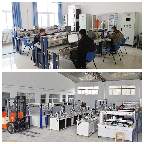
MR482E Set Of Equipment "Theory Of Electrical Circuits" Electrical Lab Equipment School Teaching Equipment
I.Product Overview
1.1 Overview
"Theory of electrical circuits" equipment kit is a set of experimental equipment specially used for teaching courses such as "Basic Theory of Electrical Engineering" and "Electrical Technology". It adopts an advanced design concept, and the experimental panels can be freely replaced to adapt to different training requirements. The experimental instruments have high precision, and all power and measuring instruments are equipped with reliable personal safety protection systems to ensure the safety of use.
This practical training device is suitable for teaching multiple courses, has good expansibility, and can be extended to other training contents. The front of the experimental hanging box is equipped with schematic diagrams and symbols to help students better understand circuit design. The experimental circuit is designed in unit circuit mode, and each unit circuit is constructed based on basic circuit principles to facilitate students to master various electrical training contents.
In short, the "Theory of electrical circuits" equipment kit is a set of comprehensive, safe, reliable, and easy-to-use electrical experimental teaching equipment that can meet the teaching needs of multiple courses, help students deeply understand circuit principles, and improve operational abilities.
1.2 Features
Advanced design: The experimental bench adopts advanced design concepts, and the experimental panels can be freely replaced to adapt to different training requirements.
High-precision instruments: The experimental instruments have high precision, and all power and instruments have reliable personal safety protection systems.
Wide applicability: It is suitable for teaching courses such as "Basic Theory of Electrical Engineering" and "Electrical Technology". Due to its good expansion ability, it can also be used for other training contents.
Clear schematic diagrams and symbols: The front of the experimental hanging box is equipped with schematic diagrams and symbols to help students better understand circuit design.
Unit circuit mode: The experimental circuit is designed in unit circuit mode. Each unit circuit is constructed based on basic circuit principles, making it easier for students to master various electrical training contents.
II.Performance Parameter
Input power: three-phase three-wire 220V±10% 50Hz
Weight: 86Kg
Overall machine capacity: < 2.0KVA
Working conditions: Ambient temperature: -10℃~+40℃ Relative humidity: <85% (25℃)
Size: 1400mm*520mm*1280mm
III.Components List and Detailed Introduction
3.1 Main Part
Number Name

1 Panel hanging box
2 Power box
3.2 Power box part
Number Name
1 Breaker
2 Emergency button
3 Three-phase AC 380V output module
4 Three-phase AC 12V output module
5 Single phase AC 5/12V output module
6 DC 5/12V output module
7 DC 0-36V adjustable DC constant voltage source module
8 Six-hole European socket module
3.3 Equipment configuration list
Number Name Quantity
Component 1 500W diode module 1
Component 2 Superposition Law Module 1
Component 3 Resistor module 1
Component 4 Law of reciprocity module 1
Component 5 Inductor module 1
Component 6 Three-phase power analyzer module 1
Component 7 AC current and voltage test module 1
Component 8 Resistor star-delta equivalent replacement module 1
Component 9 DC current and voltage test module 1
Component 10 Potentiometer module 1
Component 11 Function generator module 1
Component 12 Capacitor module 1
Component 13 Kirchhoff module 1
Component 14 Thevenin and Norton's Laws Module 1
Component 15 Osr 's Law Module 1
Component 16 Pressure dividing and shunt module 1
3.4 Accessories
Number Name Quantity
1 4mm electrical cable 1 meter double-head blue 2
2 4mm electrical cable 1 meter double-head green 2
3 4mm electrical cable 1 meter double-head black 10
4 4mm electrical cable 1 meter double-head red 10
5 4mm electrical cable 1 meter double-head yellow 10
6 Oscilloscope 1

7 Digital multimeter 1
8 Conversion socket 1
9 Three-phase auto-voltage regulator 1
IV.Experiment List
Experiment 1 Verification of Ohm’s Law
Experiment 2 Resistance Characteristics
Experiment 3 Capacitance Characteristics
Experiment 4 Inductor Characteristics
Experiment 5 Verification of Kirchhoff’s Law
Experiment 6 Verification of resistor voltage division and current shunt characteristics
Experiment 7 Verification of resistance star-delta equivalent conversion
Experiment 8 Power Calculation
Experiment 9 Verification of the superposition principle
Experiment 10 Verification of Thevenin’s Theorem and Norton’s Theorem
Experiment 11 Verification of the Reciprocity Theorem
Experiment 12 Node equation
Experiment 13 Loop Equation

