Whatsapp: 0086-15153106200
E-mail: admin@minrry.com 

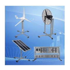
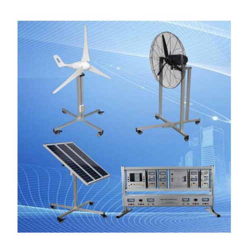
MR322E Wind Power And Solar Power Generation Training Equipment Didactic Equipment Electrical Lab Equipment
Product Instruction Book
I. Equipment Overview
1 Introduction
1.1 Overview
This training system simulate demo wind and solar generate electricity process, enable students to learn wind and solar generate electricity. Wind driven generator is driven by fan, solar energy panel is driven by high work power metal halide. This trainer cultivate students hand on ability, it’s suitable for engineering university, training institute, technical schools.
1.2 Feature
(1)This trainer use aluminum column structure, with inner integrated measurement meters, there is universal wheels at the bottom, it’s easy to move.
(2) It can do many experiment circuit and components, students can combine them to different circuit, do different experiments and training content.
(3) Training workbench with safety protection system.
2. Performance parameter
(1) Wind power generation set: wind power generation is consisted of fan unit and air-blower unit, it adopts aluminum profile structure, the bottom of equipment is with universal wheels, the boundary dimension of fan unit is 800mm*800mm*1500mm(length× width× height), the boundary dimension of air-blower is 800mm*800mm*1500mm(length× width× height).
(2) Solar power generation device: full aluminum structure, adjustable photovoltaic panel, boundary dimension is 800mm*800mm*1200mm(length× width× height).
(3) Power box unit: aluminum profile structure, aluminum hanging box , boundary dimension 1080mm×300mm×740mm(length× width× height).
(4) Single solar energy cell plate:
Rated peak value work power: 20Wp
Short circuit current:1.9A
Peak value current:1.7A
Open circuit voltage:18.5V
(5) Fan technical specifications:
Fan type: horizontal direction toward
Start speed: 2.5 meters/second
Rated fan speed:10 meters/second
Maximum anti wind speed:40meter/second
Rated work power: 200-500W
Wind direction adjust: auto adjust
(6) Battery technical specification:
Voltage:12V
Volume:12Ah
Battery lost electricity:10V±1V
Executive standard: GB/T 9535
Relative humidity: 35~85%RH(Non-condensate)
(7) Work condition:
Temperature-10~+40℃
Temperature≤80℃
Environment air: no corrosivity air, no fuel air, no large quantity of conductive dust
(8) Power:
Consumption: ≤5000W,
Work power: AC220±5%, DC12V/24V
Work mode: continuous
Power supply: connect in series or in parallel
Work mode: continuously
3. System introduction
This system is consisted of four parts: wind power system, photovoltaic power generation system, control system and inverter system. The wind power system is consisted of air-blower, generator and battery. Photovoltaic power system is consisted of photovoltaic cell panel and battery. Control system is made up of wind and solar power generation controller. Inverter system is made up of frequency inverter and load unit.
Simulative wind power generator, this system adopts horizontal shaft permanent magnet synchronous generator, it adopts air-blower to simulate natural wind, air-blower can select three wind speed, this system can simulate the change of wind direction and wind power through changing the speed and location of air-blower, then it can detect the generation effect under the corresponding condition. Simulation wind power generator is as shown below.
Simulation wind power generator
As shown above, the left picture is wind power generator, the wind power generator output is three phases AC 12V, output terminal connect to the connection box which located in the underneath of equipment. Right picture is air-blower unit, its power supply is single phase AC 220V,50Hz, when it working, connect the pedestal of two portion together through profile connecting rod. As shown below.
Connecting mode of simulation wind power generator
2. Simulative photovoltaic power generation system: this system adopts three pieces of 18V,20W solar panel, it can carry out series and parallel connection according to different system voltage, it can simulate the sunlight location through adjusting the relative location with photovoltaic panel, then it’s easy to simulate demonstration of various sunlight condition. Simulation photovoltaic power generator as shown below.
The output of photovoltaic cell panel connect to connecting box which located in the rear of device, output it through safety terminal. The rated output voltage of single block photovoltaic cell panel is 18V, three pieces of cell panel can operate individual, and it also can operate in parallel.
Simulation photovoltaic power generator
3. Battery set: it is consist of two pieces of 12V/12AH maintenance-free no-service battery, it also can connect in parallel as 12V200AH system, it also can connect in series as 24V/100AH system, it can enhance the understanding of battery series and parallel connection. Battery integrated in the internal of power box, battery output terminal connect to power box panel. In the picture, 1 and 2 are the battery output portion, it output through red and black terminal.
Power box battery
4. Controller hanging box: this hanging box adopts industrial charge controller, it can control the electric power of wind power generator photovoltaic panel to charge for the battery, panel indicator light display the controller working condition, it can check the system operation parameter, and operator can set the parameter by himself, and it has thorough overcharge protection, overcurrent protection function. Controller hanging box as shown below.
In the picture, terminal 1 and 2 are battery incoming end, battery can be series and parallel connected in it, input voltage is 12V or 24V.
Terminal 3 and 6 are fuse. Terminal 4 and 5 are controller output terminal, ( attention: controller output terminal is unable to connect to high-power electrical machine).
Terminal 7 is photovoltaic cell panel input terminal, terminal 8 is wind power generator input terminal.
Controller hanging box
(1) Controller operation matters and attention
a. Strictly prohibit inversely connect the photovoltaic module and battery
b. Strictly prohibit photovltaic module and battery direct short circuit
c. Strictly prohibit electromotor drive the generator, DC motor, switch power supply and other mode to simulate the wind power generator to carry out charging effect detection, if it cause the damage of controller because of it, manufacture don’t responsible for it.
d. Before connect to battery, please measure the battery voltage using multimeter, in order to make sure the voltage exceed the 80% of rated voltage. If the voltage under the 80% of rated voltage, it may damage the controller.
e. If it is 12 V system, battery voltage should not lower than 9V.
f. If it is 24V system, battery voltage should not lower than 18V.
g. The open-circuit voltage of photovoltaic module is not higher than the double times of battery set voltage.
h. The working voltage of photovoltaic module not lower than the 1.5 times of battery voltage.
(2) Controller panel buttons instruction
Controller panel as shown below:
A. Battery charging indicator light: indicate the charging condition.
B. Battery voltage indicator light: indicate the battery voltage condition and system fault
C. Power supply output indicator light: indicate the output power supply condition
Controller panel picture
Indicator light condition explanation
Indicator light Condition Implication
LED light
Green Extinguish Uncharged
Flicker Charging
LED light
Red Normally no Battery undervoltage
Flicker Battery overvoltage
Extinguish Battery voltage is normal
LED light
Green Normally on It has DC power supply output
Flicker It does not have DC power supply output
Extinguish Load short circuit or power overload
(1) Controller connection
Step 1: connect to battery
Warning:
A. If the battery positive and negative electrode terminal and lead which connect to positive and negative electrode will lead to short circuit, it may cause fire or explode. The machine must be operated with care.
B. If the battery voltage is lower than 9V, operator strictly prohibit to insert to controller, such serious insufficient voltage inferior-quality battery will damage the controller, if it cause product damage because of the above reason, manufacture don’t responsible for the quality guarantee and joint liability!
Warning:
A. Before connect battery, please measure the battery voltage using multimeter.
B. For 24V system, make sure the battery voltage not lower than 18V.
C. For 12 V system, make sure the battery voltage not lower than 9V.
Controller can automatic distinguish 12 V or 24V system according to battery voltage
Please attention:
If the battery voltage between 16V and 17V, those voltage are controller distinguish dead zone, controller will not work properly, please attention.
Make sure all the connection are correct, then connect to safety switch, don’t connect to safety switch before wiring.
Step 2: connect to load
Controller load terminal can connect to DC power equipment which rated working voltage the same as the battery rated working voltage, controller will power up the load using battery voltage
Connect the positive and negative electrode of load to the load connection terminal. load terminal may have voltage, so when you wiring, please carefully, avoid cause short circuit. We suggest connect a safety device on the positive electrode lead or negative electrode lead. During the installation, don’t connect to safety device. After installation, make sure all the wiring are correct, then connect to safety device. If the load connection through switchboard, each load circuit should individual connect safety device, all the load current is not higher than the rated current 10A of controller. Load can be DC LED street lamp, monitoring equipment, etc.
Step3: connect photovoltaic module
Warning:
A. Photovoltaic module may generate very high voltage, when you wiring, please carefully, protection from electricity.
B. Controller can use 12 V and 24V Off-grid sol