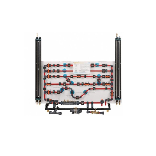
MR-HM 150.11 Losses in a pipe system teaching equipment didactic equipment lab fluid mechanics equipment Description • pressure losses in the piping system • pressure measurement without interaction via annular chambers • transparent measuring objects for determining flow rate Pressure losses occur during the flow of real fluids due to friction and turbulence(vortices). Pressure losses in pipes, piping elements, fittings and measuring instruments (e.g. flow meter, velocity meter) cause pressure losses and must therefore be taken into account when designing piping systems. MR-HM 150.11 allows to study the pressure losses in pipes, piping elements and shut-off devices. In addition, the differential pressure method is presented for measuring the flow rate. The experimental unit contains six different pipe sections capable of being shut off individually. The pipe sections are equipped with piping elements such as bends, elbows and branches. In one pipe section, different shut-off devices and measuring objects are installed to determine the flow rate. The measuring objects are made of transparent material and provide excellent insight into the inner structure. The pressure measuring points in the piping system are designed as annular chambers. This creates a largely interference-free pressure measurement. The experiments measure the pressure losses in pipes and piping elements,such as branches and bends. The opening characteristic of the shut-off devices are also recorded. The pressures are measured with tube manometers. The experimental unit is positioned easily and securely on the work surface of the HM 150 base module. The water is supplied and the flow rate measured by MR-HM 150. Alternatively, the experimental unit can be operated by the laboratory supply. Learning objectives/experiments • pressure losses in pipes, piping elements and fittings • how the flow velocity affects the pressure loss • determining resistance coefficients • opening characteristics of angle seat valve and gate valve • familiarisation with various measuring objects for determining flow rate: · Venturi nozzle · orifice plate flow meter and measuring nozzle Specification [1] investigation of pressure losses in piping elements and shut-off devices [2] different measuring objects for determining flow rate according to the differential pressure method [3] six pipe sections capable of being individually shut off, with different piping elements: sudden contraction, sudden enlargement, Y-pieces, T-pieces,corners and bends [4] one pipe section to hold interchangeable shutoff/measuring objects [5] measuring objects made of transparent material: Venturi nozzle, orifice plate flow meter and measuring nozzle [6] shut-off devices: angle seat valve, gate valve [7] annular chambers allow measurement of pressure without interaction [8] 2 twin tube manometers for measuring the pressure difference [9] flow rate determined by MR-HM 150 base module [10] water supply using MR-HM 150 base module or via laboratory supply Technical data Pipe section to hold fittings or measuring objects • 20x1,5mm, PVC Pipe sections Inside diameter: d • straight: d=20x1,5mm, length: 800mm, PVC • sudden contraction: d=32x1,8-20x1,5mm, PVC • sudden enlargement: d=20x1,5-32x1,8mm, PVC • with 2x Y-piece 45° and 2x T-piece • with 2x 90° elbow/bend: d=20x1,5mm, PVC and 2x 45° elbow: d=20x1,5mm, PVC 2x twin tube manometers: 0…1000mmWC Measuring ranges • pressure: 0…0,1bar LxWxH: 1550x640x1300mm Weight: approx. 58kg Required for operation MR-HM 150 (closed water circuit) or water connection,drain Scope of delivery 1 experimental unit 2 shut-off devices (angle seat valve, gate valve) 1 Venturi nozzle 1 orifice plate flow meter or measuring nozzle 1 set of hoses 1 set of tools 1 set of instructional material